Setting up RS-232 on a Raspberry Pi
Anthony Sorace
a.9srv.net
Strand 1 Technologies
ABSTRACT
The Raspberry Pi can be configured to treat two of its GPIO pins as a uart. This provides a ttl uart, which is much less common than RS-232 on peripheral devices or for talking between systems. An inexpensive converter can give a Raspberry Pi a RS-232 serial port.
Introduction
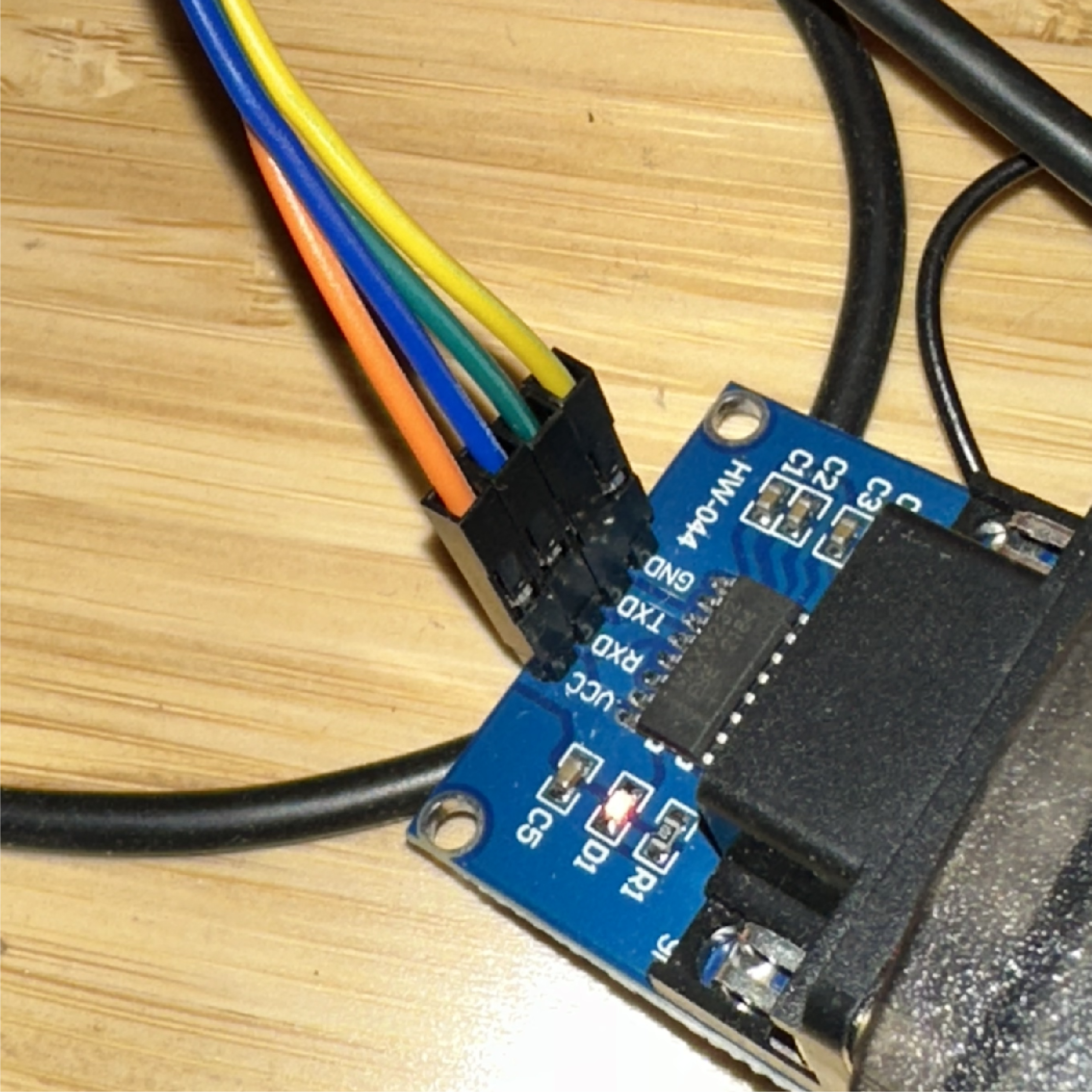
To convert between TTL and RS-232 signaling, an adaptor is needed. I used a module from DaFuRui¹ which is based upon the very popular MAX3232 chip. The build quality on the module seems good and it is at least relatively tolerant of electrical errors (see below). Assuming your Raspberry Pi already has the GPIO headers in place, you’ll only need four F/F jumper wires to connect the module. If the GPIO header is not present, you can add the 40-pin header or directly wire the connection to only the relevant pins (see below).
This works on any (non-pico) model Raspberry Pi.
Configuring the hardware
We need to connect four wires from the DaFuRui module to the Raspberry Pi: one each for 3.3V power², ground, transmit, and receive.
The DaFuRui module exposes pins for these as VCC, GND, TXD, and RXD, respectively. Attach a jumper wire to each of these.
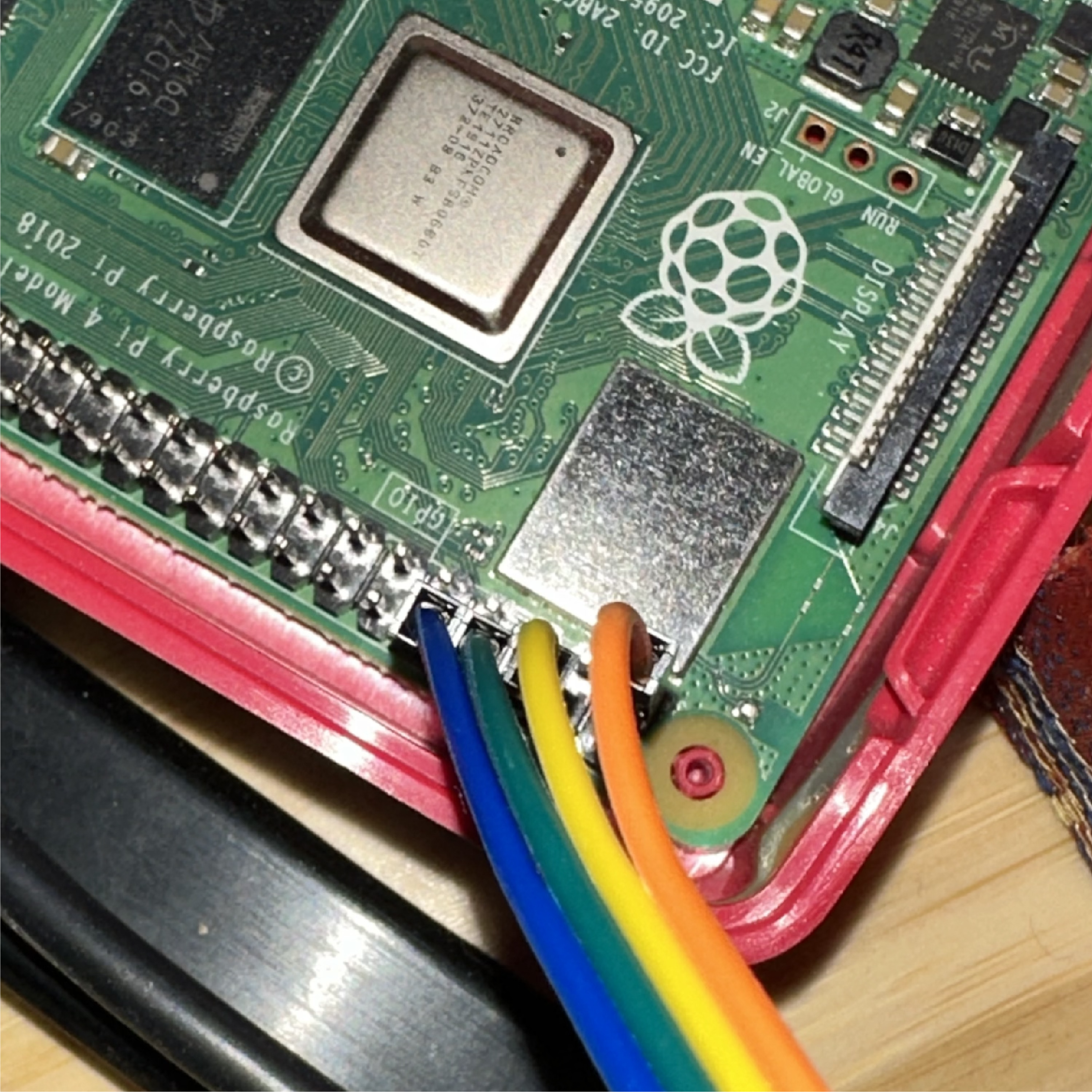
On the Raspberry Pi’s GPIO header, these correspond to pins 1, 10, 8, and 6. The numbering and relative placement of these pins are the same on all (non-pico) Pi, including the original Raspberry Pi with the shorter GPIO header and Pi Zero models.
Other options exist for connecting VCC and GND if those pins are unavailable, such as being used by another device; see https://pinout.xyz.
Configuring the software
First we will need to tell the Raspberry Pi bootloader to enable the uart by editing config.txt on the boot volume. If you’re doing this on the pi running Plan 9, run c: to mount the boot dos partition, then edit /n/c/config.txt to add this line:
enable_uart=1
Reboot the pi. You should be able to read /dev/eia0status to get the current state of the uart, and set the baud rate on the device using something like:
echo b9600 > /dev/eia0ctl
See uart(7) for details.
Testing the results
The serial port at /dev/eia0 should now be ready for normal use. Test by connecting to another system with a known configuration. A representative session follows.
:; cat /dev/eia0status
b115200
dev(0) type(0) framing(0) overruns(0) berr(0) serr(0)
:; echo b9600 > /dev/eia0ctl
:; con -r /dev/eia0
Incorrect configuration checksum;
Setting NVRAM parameters to default values.
Setting diag-switch? NVRAM parameter to true
Probing CPU FMI,MB86904
The IDPROM contents are invalid
Initializing 40 megs of memory at addr 0
Boot device: /iommu/sbus/ledma@4,8400010/le@4,8c00000 File and args: /kona
Internal loopback test -- Did not receive expected loopback packet.
Can’t open boot device
ok >>> q
:;
Notes
¹ https://www.amazon.com/gp/product/B07Z5Y1WKX/
² When I first wired up the module, I connected VCC to the raspberry pi’s pin 4. This will power the module, but at 5V instead of the rated 3.3v. It did not seem to do any damage for the few minutes I had it connected this way, but the unit did get very warm very quickly. I did not test data transmission under this configuration.